|
|
|
|
|
|
|
|
|
|
|
|
|

INTRODUCTION
In order to have as little interferences at the entrance of the amplifier, it is necessary to "protect" the electric signal generated by the microphones. Indeed, all the wires of the electronic and the jack cable can pick up electromagnetics waves in the environment, such as 50-60 Hertz sector. These parasites are then amplified and we could hear an unpleasant "bzzz" in the amplifier. On the principle of a Faraday Cage , it is necessary to "lock" the electronics of the guitar in a "box" to stop, or at least limit the passage of electromagnetics interferences. On the stratocaster-like guitars, this box is formed by electronics cavities, dug in the body, and closed by the pickguard (Figure 1). That's why we must make a shielding on the pickguard, ie cover it with a conductive surface (paint or self adhesive metal tape) . In this tutorial, the pickguard is wood made, and the conductive surface is made of self adhesive aluminum tape.

NEEDED EQUIPMENT
- One pickguard.
- One cutter.
- Some pickguard screws to drill the screws holes on the pickguard.
- One cloth to smooth the surface.
- Scissors.
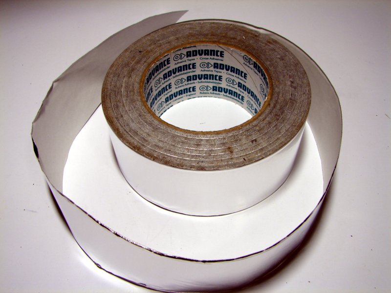
- One self adhesive aluminium or copper foil tape, easy to find in hardware store.
- One pen or other thing which can enter in the potentiometer holes.
- One ohmmetter to measure the conductivity of the surface.
Intro |
Equipment |
Stage 1 |
Stage 2 |
Stage 3 |
Stage 4 |
Stage 5 |
Stage 6 |
↑
Top
- One pickguard.
- One cutter.
- Some pickguard screws to drill the screws holes on the pickguard.
- One cloth to smooth the surface.
- Scissors.
- One self adhesive aluminium or copper foil tape, easy to find in hardware store.
- One pen or other thing which can enter in the potentiometer holes.
- One ohmmetter to measure the conductivity of the surface.


STAGE 1 : CUT AND STICK THE FIRST ALUMINIUM STRIP
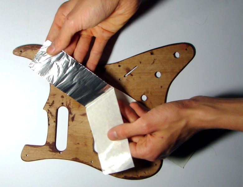
Cut a strip of aluminum taking roughly measure with a side of the pickguard (Figure 5).
Be careful not to bend too aluminum removing the protective paper (Figure 6).
Stick the strip following the vertical of the pickguard, smoothing the surface bit by bit.
Intro |
Equipment |
Stage 1 |
Stage 2 |
Stage 3 |
Stage 4 |
Stage 5 |
Stage 6 |
↑
Top
Cut a strip of aluminum taking roughly measure with a side of the pickguard (Figure 5).
Be careful not to bend too aluminum removing the protective paper (Figure 6).
Stick the strip following the vertical of the pickguard, smoothing the surface bit by bit.

STAGE 2 : CUT THE EXCEED ALUMINIUM AND SMOOTH THE SURFACE
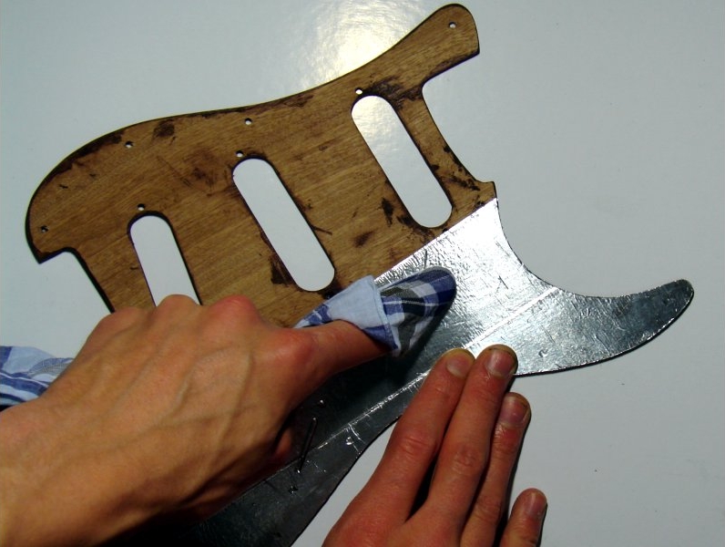
Turn the pickguard and cut exceed aluminium with the cutter (Figure 7).
With the cloth, smooth the surface to avoid veins (Figure 8 & 9).
Intro |
Equipment |
Stage 1 |
Stage 2 |
Stage 3 |
Stage 4 |
Stage 5 |
Stage 6 |
↑
Top
Turn the pickguard and cut exceed aluminium with the cutter (Figure 7).
With the cloth, smooth the surface to avoid veins (Figure 8 & 9).


STAGE 3 : COVER THE REST OF THE SURFACE WITH ALUMINIUM STRIPS, TESTING CONDUCTIVITY
Overlap strips of aluminum by about 5 mm. Smooth well and cut the exceed of aluminium (Figure 10 & 11). However, leave covered holes : they will be cutted to the next stage (Figure 13).
Test conductivity bit by bit using the multimeter : over the conductivity is high, the better (Figure 12).
Intro |
Equipment |
Stage 1 |
Stage 2 |
Stage 3 |
Stage 4 |
Stage 5 |
Stage 6 |
↑
Top
Overlap strips of aluminum by about 5 mm. Smooth well and cut the exceed of aluminium (Figure 10 & 11). However, leave covered holes : they will be cutted to the next stage (Figure 13).
Test conductivity bit by bit using the multimeter : over the conductivity is high, the better (Figure 12).


STAGE 4 : CUT THE PICKUPS HOLES
Press around the holes before cutting, to mark the cut line.
Intro |
Equipment |
Stage 1 |
Stage 2 |
Stage 3 |
Stage 4 |
Stage 5 |
Stage 6 |
↑
Top
Press around the holes before cutting, to mark the cut line.


STAGE 5 : CUT THE POTENTIOMETERS HOLES
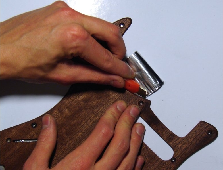
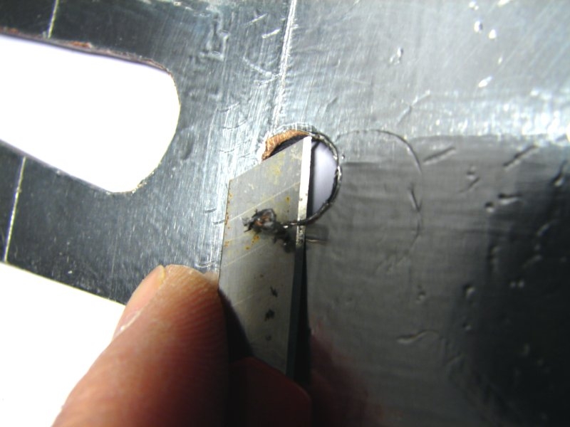
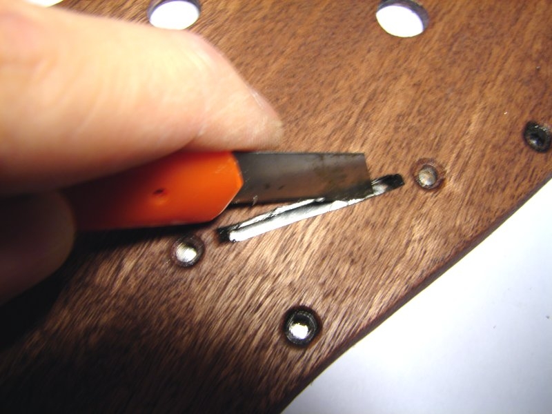
Begin the potentiometers holes with the tip of the cutter (Figure 17).
Then, using the pen, drill holes potentiometers (Figure 18).
Finally, cut the surplus of aluminum with the cutter (Figure 19).
Intro |
Equipment |
Stage 1 |
Stage 2 |
Stage 3 |
Stage 4 |
Stage 5 |
Stage 6 |
↑
Top
Begin the potentiometers holes with the tip of the cutter (Figure 17).
Then, using the pen, drill holes potentiometers (Figure 18).
Finally, cut the surplus of aluminum with the cutter (Figure 19).


STAGE 6 : FINISHING
To drill the screw holes, simply screw a screw pickguard (Figure 20).
Scrape the way around the pickguard with the cutter, to remove the exceeding aluminium (Figure 22).
The pickguard is now shielded and ready to serve as support for the electronic circuit.
To drill the screw holes, simply screw a screw pickguard (Figure 20).
Scrape the way around the pickguard with the cutter, to remove the exceeding aluminium (Figure 22).
The pickguard is now shielded and ready to serve as support for the electronic circuit.


Intro | Equipment | Stage 1 | Stage 2 | Stage 3 | Stage 4 | Stage 5 | Stage 6 | ↑ Top